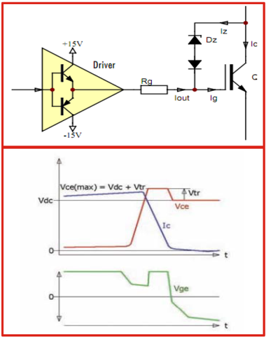
Active Clamping(for over-voltage protection) has been widely used for many years to limit the collector-emitter voltage of an IGBT during the turn-off event . The IGBT is partially turned on as soon as its collector-emitter voltage exceeds a pre-defined threshold. The IGBT is then maintained in linear operation, thus reducing the fall rate of the collector current and therefore the collector-emitter over-voltage.
Basic(conventional) active clamping topologies implement a single feedback path from the IGBT’s collector through transient voltage suppressor devices (TVS) to the gate
The TVS placed between collector and gate ensures that the gate is switched on again when a defined voltage is exceed at the collector.The IGBT then becomes conducting and the result is a reduced IGBT turn-off over-voltage
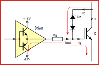
The turn-off transistor of the driver is switched on ,this reduce the charge that flows from TVS path to IGBT gate
This impact the IGBT conducting and the performance of over-voltage protection
Of course you can increase gate resistance to relieve effect, but sacrifice efficiency
Advanced Active Clamping
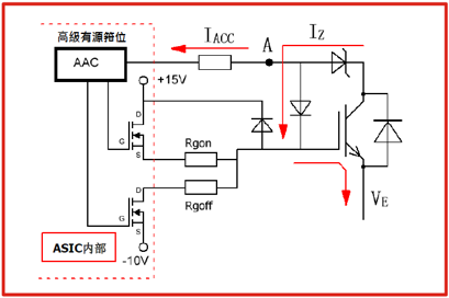
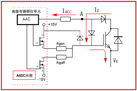
Most SCALE-2 products support Power Integrations' Advanced Active Clamping, where feedback is also provided to the driver’s secondary side at pin ACL
The turn-off MOSFET of the driver stage is progressively switched off in order to reduces the charge that flows away from the IGBT gate to COM over the turn-off gate resistor
This improve the effectiveness of the active clamping and reduce the losses in the TVS
The gate resistor is no longer responsible for the active clamping and no impact with efficiency
最基本的主動箝位電路
- 下圖所示為最基本的主動箝位電路,只需要TVS和普通快恢復二極體即可構成
- 其原理是:當集極電位過高時,TVS崩潰導通,有電流流進柵極,柵極電位得以抬升,從而使關斷電流(dIC/dt or dID/dt)不要過於陡峭,進而減小VCE(or VDS)電壓尖峰
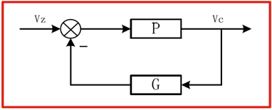
- 這個箝位的過程的本質是一個負回授,如下圖示。給定是TVS的擊穿點,被控對象是集極電位
基本主動箝位電路的缺點
- 上面所提到的基本的主動箝位電路是有明顯的缺點的,如下圖所示
- 首先明確,主動箝位電路工作在IGBT關斷的瞬間,在這個時刻裡,IGBT驅動器的最後一級推動級的關斷電晶體是開著的,而TVS的電流少部分流入柵極,絕大部分則被這個電晶體旁路掉了
- 顯然,由於這個支路的阻抗很低,因此TVS的電流大部分被這個電晶體“吃掉了”。TVS的電流增大導致其擊穿電壓持續上升箝位效果就大打折扣了或者說電路的有效性降低
- 其次,TVS管的功耗非常大,導致必須選取封裝較大的TVS,物料比較貴,且占PCB板的面積較大,誤差偏大,雜散電容過高等缺點
- 這線路問題可以透過增加RG來減小這被吃掉的電流部分,不過這也表示必須要犧牲效率來改善這情況,不是非常理想
以下為PI推出的“Advanced Active Clamping”
- 下圖為PI推出的基於SCALE2晶片組的Advanced Active Clamping的功能示意圖
- 當TVS被擊穿時,電流IAAC會流進ASIC的AAC Pin。內部會根據IAAC的大小操縱下臂MOSFET。當該電流大於40mA時,下臂Mosfet開始被線性地關斷,當電流大於500mA時,下管Mosfet完全關閉。(以上電流數值為概略值)
- 此時柵極處於開路狀態,Iz會更有效的向柵極電容充電,使柵極電壓從米勒平臺回到+15V,從而使關斷電流變緩慢,達到電壓箝位的效果。這個電路的特點是TVS的負載非常小,TVS的工作點非常接近額定點,箝位的精準度及電路的有效性大大提高
主動箝位電路的調試及觀測方法
- 在調試主動箝位電路時,如果需要觀察主動箝位功能是否有動作,需要:
- 誘發主動箝位
- 觀測柵極波形或者A點波形
- 主動箝位動作發生,在集電極上必須有足夠高的電壓,誘發的辦法是,將母線電壓抬得較高,較接近箝位點,例如箝位點在850V,則將母線調至750V或800V。然後用雙脈衝做2倍額定電流關斷,或者短路電流的關斷,此時會產生較大的電壓尖峰,就能觀察到主動箝位動作
- 用示波器觀察GE波形,在電流Ic下降的過程中,柵極會發生上翹,且電流斜率會輕微變小,這是典型的主動箝位動作
根據產品的manual,用示波器觀察A點(右圖)波形,參考COM(圖中的-10V),該點電位超過1.3V時,下管mosfet開始線性關斷,當該電位達到20V時,下管mosfet完全關斷。此時柵極完全懸空,需要柵極箝位二極管箝住柵極電位,不至於超出15V
Advanced Active Clamping 的實際表現
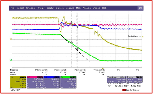
- 下圖是關斷7500A電流(短路測試)時產生的主動箝位動作
- 黃線C1為Vge
- 藍線C3為Vce
- 綠線C4為Ic (2KA/div)
- 可以看出
- 柵極波形從15V下跳時,Ic開始下降,Vce(C3)同時產生了電壓尖峰
- 電壓尖峰最高到達約2600V,然後被鉗在2500V
- 電流在下降過程中的斜率被改變了
- 通常需要500ns就能關斷的電流用了1.5μs才被完全關斷
主動箝位電路的關鍵點
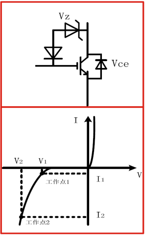
- 下面第一張圖可知,當主動箝位電路工作時,Vz ≈ Vce,也就是說,TVS上的電壓就是IGBT集電極上的電壓,換句話說,能控制住Vz,就能控制住Vce
- 下面第二張圖為TVS管的外特性,其中有2個不同的工作點。工作點1的擊穿電流比較小,工作電壓比較低,而工作點2的工作電壓則比較高
- 在主動箝位應用中,我們則希望TVS管能工作在額定的擊穿點附近,而不希望TVS被深深地擊穿。
- 如果TVS被擊穿後電流劇烈增大,那麼TVS則會從工作點1下探至工作點2,其電壓也會強烈上升,這意味著IGBT的CE電壓也會上升,這時就達不到IGBT箝位的效果了
